
Wiring harnesses act as the central nervous system for modern hardware. From automotive engine bays to automated industrial control cabinets, these assemblies transmit power and data continuously. Despite being perceived as simple components—just wire, terminals, and connectors—harnesses are frequently the root cause of systemic hardware failures. When a piece of machinery goes offline due to electrical faults, the culprit is rarely the main processing unit; it is usually a compromised physical connection.
Understanding the exact mechanisms behind these physical layer failures requires analyzing the mechanical, environmental, and electrical stresses acting upon the assembly during its lifecycle. Diagnosing these root causes early in the engineering phase allows teams to specify better materials and manufacturing tolerances, preventing expensive field recalls and system downtime.
Heat is the primary enemy of polymer insulation. Wires are often routed near heat-generating components like motors, exhaust systems, or high-power transformers. Over time, elevated temperatures accelerate the outgassing of plasticizers within common PVC insulation, causing the jacket to become brittle, crack, and eventually expose the bare conductor. This creates an immediate risk for short circuits and arcing.
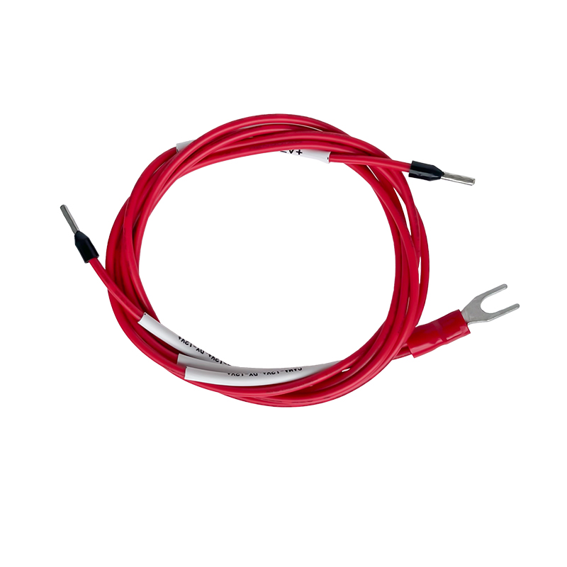
The Arrhenius equation dictates that for many common insulating polymers, the expected lifespan is reduced by half for every 10°C increase in continuous operating temperature above the rated baseline. This makes material selection critical. For example, relying on standard 80°C-rated wire in an enclosure that frequently reaches 85°C guarantees premature failure. Upgrading to a Custom UL1015 20AWG Wire Harness Assembly provides a robust defense mechanism, as the UL1015 specification carries a 105°C temperature rating. This additional thermal headroom significantly extends the operational lifespan in harsh environments by resisting the oxidative degradation that destroys lesser PVC blends.
| Insulation Type | Max Temperature Rating | Typical Application Environment | Failure Mechanism at Over-temp |
|---|---|---|---|
| Standard PVC (UL1007) | 80°C | Consumer electronics, mild indoor | Plasticizer loss, embrittlement, cracking |
| High-Temp PVC (UL1015) | 105°C | Industrial machinery, internal appliances | Gradual hardening over prolonged extreme exposure |
| XLPE / Teflon (PTFE) | 125°C - 200°C+ | Automotive under-hood, aerospace | Resists heat but vulnerable to cold-flow or abrasion |
A crimp is not simply squishing metal onto a wire; it is a cold-welding process that requires immense precision. The goal is to deform the wire strands and the terminal barrel to create a single, solid mass of metal that is entirely gas-tight. If corrosive gases or oxygen can penetrate the crimp joint, oxidation will occur, raising the electrical resistance of the connection.
Crimping errors generally fall into two categories: under-crimping and over-crimping. An under-crimped terminal leaves microscopic voids between the strands, leading to high electrical resistance, localized heating, and eventually thermal runaway. An over-crimped terminal physically damages the wire strands, reducing the effective cross-sectional area and creating mechanical weak points that break under vibration.
To avoid these dangerous voltage drops in power-critical circuits, engineers must specify a Low Impedance Crimp Terminal Wire Harness. These assemblies are manufactured under strict quality control, utilizing automated press equipment that monitors crimp force in real-time. By verifying the exact crimp height and utilizing micrograph cross-section analysis, the manufacturer ensures optimal compression, yielding a connection with near-zero added impedance.
| Crimp Condition | Mechanical Strength (Pull Force) | Electrical Resistance | Long-Term Reliability Risk |
|---|---|---|---|
| Under-Crimped | Low (Wire pulls out easily) | High (Oxidation prone) | Thermal runaway, intermittent connection |
| Optimal Crimp | Maximum (Exceeds wire break force) | Minimum (Gas-tight cold weld) | Stable over decades of use |
| Over-Crimped | Low (Strands shear at crimp base) | Moderate to High | Mechanical fracture under vibration |
In applications involving motors, moving structural components, or transportation, constant vibration wreaks havoc on wiring interfaces. When a wire is improperly secured, it experiences cyclic bending stress. Since copper work-hardens, the continuous flexing eventually causes the copper strands to snap cleanly off near the termination point. Proper routing mandates the use of strain relief—securing the harness with clamps or zip-ties near connectors to transfer the mechanical load off the actual electrical joint and onto the structural chassis.
Vibration also introduces an invisible killer: fretting corrosion. This phenomenon occurs at the microscopic level inside mated connectors. Micro-vibrations cause the metal pins to rub against each other, scraping away thin layers of oxide. The exposed bare metal immediately re-oxidizes, and the process repeats. Over thousands of hours, this microscopic scraping builds a thick layer of non-conductive oxide debris between the contacts. The system begins experiencing ghost faults—momentary drops in sensor data or sudden voltage dips. Utilizing heavier plating (like gold over nickel) or specialized contact lubricants can mitigate fretting, but routing harnesses to minimize resonant frequency transmission is the best physical defense.
Field installations inside electrical cabinets and control panels represent another major failure point. Technicians frequently strip stranded wire and insert it directly into screw-clamp terminal blocks. As the screw tightens down, it exerts rotational and crushing forces that splay the strands apart. Some strands break, effectively reducing a 16 AWG wire to an 18 AWG or 20 AWG equivalent right at the joint, completely destroying the current-carrying capacity.
Additionally, copper creeping (cold flow) under the screw pressure causes the connection to loosen over time, requiring routine maintenance to re-torque the screws. Utilizing a Pre Crimped Ferrule Terminal Wiring Harness solves this structural issue at the source. The ferrule acts as a protective copper or brass sleeve that encapsulates the delicate wire strands. When the terminal block screw is tightened, it presses against the solid body of the ferrule rather than the individual strands. This distributes the pressure evenly, prevents strand breakage, eliminates the risk of stray strands causing short circuits to adjacent terminals, and significantly reduces the maintenance burden of retightening connections.
Wiring harnesses installed in harsh environments face attacks from oils, coolants, cleaning agents, and water. A common oversight in harness design is neglecting the wire's natural tendency to act as a capillary tube. If moisture enters an unsealed connector or a damaged section of insulation, the temperature changes and pressure differentials inside the system can actively draw fluid up the inside of the wire jacket, running between the copper strands.
This capillary action can transport corrosive fluids directly into sealed electronic control units (ECUs) or expensive sensors miles away from the initial ingress point. Designing proper drip loops—routing the wire so that it dips below the connector entry point—forces fluids to drip off the bottom of the loop via gravity rather than flowing into the connector. Specifying heat-shrink tubing with internal meltable adhesive (dual-wall heat shrink) at the termination points blocks this internal fluid migration pathway.
| Environmental Threat | Primary Failure Mechanism | Engineering Countermeasure |
|---|---|---|
| Oil / Hydrocarbons | Insulation swelling, softening, and melting | Specify cross-linked elastomers or PTFE jackets |
| Moisture / Condensation | Capillary action, internal corrosion, shorts | Adhesive-lined heat shrink, drip loops, IP67+ connectors |
| Physical Abrasion | Chafing against sharp chassis edges | Corrugated loom tubing, rubber grommets, strict routing rules |
Mitigating wiring harness failures is not just about identifying the physical mechanisms; it relies heavily on implementing rigorous validation testing before the assembly reaches the field. A visually perfect harness can still hide catastrophic internal flaws. Modern quality assurance demands automated continuity testing, hi-pot (high potential) testing to verify insulation dielectric strength, and push-back testing to ensure connector pins are fully seated and locked into their plastic housings.
Engineering teams must shift from viewing wiring assemblies as commodity add-ons to treating them as complex, highly engineered subsystems. By specifying precise tolerances for crimp heights, matching the insulation material to the exact thermal environment, and enforcing strict routing parameters that account for vibration and moisture, manufacturers can practically eliminate field failures. Implementing standardized pull-force testing schedules on the assembly line ensures the mechanical integrity of every cold weld, translating physical design data directly into long-term electrical reliability.
Email : grace@smartwireconnect.com
Tel : +8613554925749
Whatsapp : +8613554925749
2-3 Floor, No. 45, Minfu Road, Shatou Industrial Zone, Shajing Street, Bao'an District, Shenzhen, Guangdong, China


©2026 Shenzhen Smart Connection Technology Co., Ltd. All Rights Reserved.
 IPv6 network supported